Tuesday, December 17, 2013

PhotoDiode

What is a photo-diode?

A photodiode is a type of photodetector capable of converting light into either current or voltage, depending upon the mode of operation.

The common, traditional solar cell used to generate electric solar power is a large area photodiode. Photodiodes are similar to regular semiconductor diodes except that are exposed (to detect UV or X-rays or visual light to reach the sensitive part of the device so that the electron excitation can take place from valence band to the conduction band, thereby developing required potential difference.

How photo-diodes are operated?

A photo-diode is designed to operate in reverse bias When photo diode is directly biased it acts like normal diode. But in reverse biased mode current through the diode depends on the brightness and you can use this relation between brightness and current for something you want your circuit to do.

Why photo-diodes are preferably used in reverse bias mode?

A photo diode is a diode and it do act as a barrier in reverse bias as in the case of diode, but in case of photo-diode as the light falls on the reverse biased PN junction there forms a discharge that discharge leads to formation of new electrons and holes, as we have electrons and holes in the reverse bias PN junction and due to the external voltage applied across a the diode leads to the reverse break down (i.e Zenner breakdown)and hence the (minority dimonated) current flows. The number of electrons and holes in reverse bias junction depends upon the discharge which in turn depends upon the light intensity and with the increase intensity of light the current through the diode in reverse biase increases. Thus in reverse biased mode current through the diode depends on the brightness and you can use this relation between brightness and current for something you want your circuit to do.

In reverse biased mode the width of the depletion layer increases thereby reduces the junction capacitance and hence causes the faster response times for the photodiode. The photocurrent is linearly proportional to the illuminance.


Wednesday, December 11, 2013

Electromagnetic Induction

Description of the phenomenon
A rapidly changing magnetic field induces electric currents to flow in a closed circuit.
magnet dropped through a coil
In the diagram above, a bar magnet is dropped vertically through a coil linked to a centre-zero galvanometer.
graph of EMF against time for a dropped magnet through a coil
A graph of coil EMF against time shows that:
When the first pole(S) falls through the coil EMF increases to a level then decreases.
When the middle of the magnet falls throught the coil, the EMF is at a minimum. No lines of force are being cut by the coil.
Maximum EMF is obtained when the second pole(N) falls through the coil. This is when the rate of cutting lines of force is highest, because the magnet is falling faster. As a result of the velocity being greater the period of high EMF is shorter.
Note that because the field direction is reversed when the poles drop through the coil, the induced current direction is also reversed. So the EMF is reversed (EMF is directly proportional to current).

Faraday's Law
Consider different sized coils when the same magnet is introduced into the body of each coil with the same velocity.
Faraday's law - diagram #1
It is found that,
Faraday's Law equation #1
So induced EMF E is directly proportional to number of turnsN,
EMI - equation #2b
Now consider just one coil and in turn introduce three magnets. The magnets are of different strengths and are introduced into the coil at the same velocity.
Faraday's Law - diagram #2
By measuring the maximum EMF and flux for each magnet, it is found that,
Faraday's Law - equation #2
So induced EMF E is directly proportional to flux φ,
EMI - equation #2c
Faraday's Law simply states:
The induced EMF in a closed circuit is directly proportional to the flux linkage.
Flux linkage Nφ is the product of flux φ and the number of turns N on a coil.
We have seen that,
em induction - equation #2
Therefore,
em induction - equation #3
Lenz's Law
The direction of the induced EMF is such that the induced current opposes the change producing it.
So when a magnetic south pole is moved towards a coil in a circuit, the face of the coil presents a south pole. The induced current is opposing the change that produced it by trying to prevent the south pole from entering the coil (by repelling it).
Lenz's law - diagram #1
Similarly, when a south pole is pulled from a coil in a circuit, the face of the coil presents a north pole. The induced current is opposing the change that produced it by trying to prevent the south pole from leaving the coil (by attracting it).
Note:
1.) How the current direction is changed by the magnet direction.
2.) On each coil face, how a line drawn between the ends of arrows(in grey) makes an 'N' and an 'S' , giving the polarity of the coils.
Neumann's Equation
This combines the proportionalities in Faraday's Law with the direction of the induced current from Lenz's Law.
As a result of the consistency of units used (SI), there is no need for a constant of proportionality.
em induction - equation #1
The minus sign is from Lenz's law, indicating the opposing nature of induced EMF and rate of flux linkage cutting.
The equation can be amended to include the rate of flux cutting dφ/dt by taking the number of coils N out of the differential.
EMI - equation #10
Flemming's Right Hand Rule
The rule describes the resulting directional motion of the induced current for a conductor moving at right angles to the field direction.
The three quantities FIELD, CURRENT AND MOTION are mutually at right angles to each other.
Flemming's Right Hand Rule
using the right hand, position the first finger, second finger and thumb to form the x,y,z axes. The highlighted letters within the words help you remember the three quantities
First finger - Field direction
seCond finger - Current direction
thuMb - Motion produced


EMF induced in a metal rod
For an induced EMF E to be produced across the length L of a metal rod, the magnetic field B, the velocity v and the major axis of the rod must all be mutually at right angles to each other.
B, L and v mutually at right angles to each other
The derivation of E = BLv :
Consider a metal rod of length L.

BLv - diagram

If the rod is travelling at a velocity v at right angles to its length then the area swept out per second is given by:
em induction - equation #4
The total flux φ threading through this area per second is the product of the area A and the flux density B.
em induction - equation #5
Substituting for the area A,
em induction - equation #6
In this case, since the total flux φ refers to 1 second, we can write :
em induction - equation #7
where dφ/dt is the rate of flux cutting.
Hence,
EMI - equation 7b

By definition, EMF (E) is equal to the rate of flux cutting,
em induction - equation #8
Therefore,
EMI - equation #9


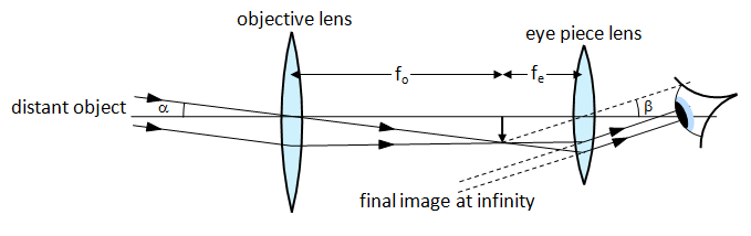
Astronomical Telescope

Diagram of Astronomical Telescope in Normal Adjustment
Disadvantages of a refracting telescope:
Lenses suffer from colour distortion – this means that when white light passes through the lens it is split into the colours of the spectrum. Because violet light refracts more than red light it is brought to a focus closer to the lens than the red light – this makes the image coloured and blurred. This effect is called chromatic aberration.
Advantages of a reflecting telescope:
Mirrors do not suffer from the colour defects of chromatic aberration.
For these reasons all the really large telescopes in the world today are reflectors.

Saturday, March 23, 2013

Adieu to Batch 2012... Fresh Batch Starts...

Adieu... to all students of Batch 2012...
Fresh Batches of ISC starts from 1st April 2013...
Timings: 5:00 pm to 6:15 pm...
All other information to be given later in the class...
Class planner XII schedule can be checked here...

Tuesday, November 13, 2012

JEE (Main)

Admission criteria to Undergraduate Engineering Programs at NITs, IIITs, Other Centrally Funded Technical Institutions, Institutions funded by participating State Governments, and other Institutions shall include the performance in the class 12/equivalent qualifying Examination and in the Joint Entrance Examination, JEE (Main). 
The Paper-1 (B. E./B. Tech.) of JEE (Main) will also be an eligibility test for the JEE (Advanced), which the candidate has to take if he/she is aspiring for admission to the undergraduate programmes offered by the IITs. 

The Application Forms of the first level exam, JEE Main 2014 have been released and will be filled online only on :
Click HERE>> 

http://jeemain.nic.in/jeemainapp/Welcome.aspx

Eligibility criteria for appearing in JEE (Advanced) - 2014:

The candidates have to first appear in Paper-1 of JEE(Main)-2014. Only 1,50,000 of the top scorers of Paper-1 of JEE(Main)-2014, including all categories, will be eligible to write JEE(Advanced) – 2014. Candidates who appeared in their qualifying examination (QE) (10+2 or equivalent) earlier than 2013 are not eligible.

Advertisement of JEE ADVANCED 2014


Sunday, November 4, 2012

Specific Heat Capacity Of Gases

Specific Heat Capacity Of Gases

Specific heat of a gas is numerically equal to the amount of heat necessary to raise the temperature of unit mass of gas by 1°C. In order to raise the temperature of unit mass of a gas through 1°C more heat will be required if the gas was kept at constant pressure than when it is at constant volume.
(i) Molar Specific heat capacity at constant Volume: The amount of heat required to raise the temperature of 1 mole of gas by 1 °C at constant volume is called the molar specific heat and it is represented by Cv.
            Cv = (ΔQ/mΔt)v = constant
By first law of thermodynamics ΔQ = ΔU + W
But W = 0 for isochoric process, then ΔQ = ΔU
by definition of specific heat ΔQ = nCvΔT
Where CV is the specific heat (for 1 mole of gas), then ΔU = nCvΔT
The relation ΔU = nCvΔT, is used to find the change in internal energy of the system and is valid for any process where a temperature change has taken place.
Consider two isotherms on the P-V diagram:
Process 1 –> 2 represents an isochoric process
Process 1 –> 3 represents an isobaric process
In both processes the temperature has changes from T1 to T2 as 2 and 3 lie on the same isotherm. Thus change in internal energ
             U1–>2 = U1–>3 = nCvΔT
(ii) Molar Specific heat capacity at constant Pressure: The amount of heat required to raise the temperature of 1 mol of gas by 1°C keeping its pressure constant, is called molar specific heat at constant pressure and it is represented by Cp,
             Cp = (ΔQ/mΔT)P  = constant
(iii) Relation between Cp and Cv: For an isobaric process by definition
From first law ΔQ = ΔU + W
=> nCPΔT = nCVΔT + W      [∴ ΔU = nCVΔT for any process]
For isobaric process
W = PΔV = nRΔT            nCPΔT = nCVΔT + nRΔT
=> CP = CV + R      or     CP ­- CV = R     (Meyer’s relation)
(iv) Relation between specific heat (CP and CV) and degrees of freedom: If f is the number of degree of freedom of a gas molecule then the internal energy of n moles of that gas is given by
U = f × 1/2 nRT            (from law of equipartition of energy)
(∴ U = f/2 kT = f/2 R/N T (for n moles) = nN × f/2 R/N T = n f/2 RT)
=> dU = f × 1/2 nRdT
Also dU = nCVdT, 
So, nCVdT = f × 1/2 nRdTf/2 R
but CP = CV + R
∴ CP = (f/2 f/2 + 1)R. This is the relation between specific heat ratio and degree of freedom.
(v) Adiabatic Expansion of an Ideal gas: As defined earlier in adiabatic process ΔQ = 0
For a system containing an ideal gas adiabatic process can happen in two ways
(i) if the system boundary is adiabatic
(ii) if the system boundary is diathermic but the process takes place so fast that their is no time for the transfer of the heat. For example, Propagation of sound in air.  
For an adiabatic process as shall be proved
PV? = a constant, here g = CP/ CV. ? is known as adiabatic constant
Since PV = nRT for an ideal gas
P = nRT/V so,
(nRT/V)Vg = Constant           ∴ TVg–1 = a constant
Proof: Let n moles of an ideal gas expand adiabatically by a small amount ΔV.
By first law   ΔQ = ΔU + PΔV
As ΔQ = 0    we have ΔU = –PΔV
But       U = nCvΔT
So,       nΔT = –(P/Cv)ΔV                                                                               …(i)
From the ideal gas law (after differentiating) ,          PΔV = VΔP = nRΔT
Replacing R by its equal, CP ­- CV leads to this,         nΔT = PΔV + VΔP/Cp – Cv        …(ii)
equating (1) and (2) with a little algebra leads to
            ΔP/P + (Cp/Cv) ΔV/V = 0            Cp/Cv = g
and integrating we have, ln P + g In V = a constant,
or PVg = a constant, hence proved.
Again g = Cp/Cv = Cv + R/CV = 1 + R/Cv = 1 + R/(1/2 fR) = 1 + 2/f
(vi) Work done in an adiabatic process (P1V1T1) to (P2V2T2)
For adiabatic process, W = –ΔU = –n CvΔT
From ideal gas equation P1V1 – P2V2 = nR (T1 – T2) = – nRT
     W = Cv(P1V1 – P2V2)/R(P1V1 – P2V2)/?–1 = nR(T1 – T2)/–1
(vii) The table shows the values of f, Cv, Cp and g for different gasses:
Nature of gas
Degree of freedom
f = (T+R+V)
Cv
Cp
g
Monatomic
3+0+0 = 3
3
5
 5/3
Diatomic
3+2+0 = 5
5
7
 7/5
Polyatomic (linear)
3+2+0 = 5
5
7
 7/5
Polyatomic
(non-linear)
3+2+1 = 6
3R
4R
 4/3
Note: At room temperature the energy associated with vibrational motion is negligible in comparison to translational and rotational KE.
Expressions For ΔU, W, And ΔQ For Different Process
Processes
Relation between thermodynamic variables
Work Done (W)
Heat Exchange (ΔQ)
Isothermal Process
(T constant)
  P∝1/V
W = 2.303 nRT log10 (V2/V1)
ΔQ = 2.303 nRT
log10(V2/V1)
Adiabatic Process
(No heat exchange)
PVg = constant
W = (P1V1 – P2V2)/(g–1) = nR(T1– T2)/(g-1)
ΔQ = 0
Isochoric   Process
(V = constant)
 P ∝T
W = 0
ΔQ = n CΔT*
(Use definition of Cv)
Isobaric Process
(P = Constant)
 V ∝T
W = P Δ V = P(V2 –V2)
W = nR (T2 –T1)
ΔQ = n CΔT*
(Use definition of Cp)

Sunday, October 21, 2012

Proof of Bernoulli Equation


The Bernoulli Equation for an incompressible, steady Fluid Flow:

The Bernoulli Equation is a statement derived from conservation of energy and work-energy ideas that come from Newton's Laws of Motion.
Statement:It states that the total energy (pressure energy, potential energy and kinetic energy) of an incompressible and non–viscous fluid in steady flow through a pipe remains constant throughout the flow, provided there is no source or sink of the fluid along the length of the pipe.
This statement is based on the assumption that there is no loss of energy due to friction.
To prove Bernoulli’s theorem, we make the following assumptions:
1. The liquid is incompressible.   
2. The liquid is non–viscous. 
3. The flow is steady and the velocity of the liquid is less than the critical velocity for the liquid.

Proof of Bernoulli’s Theorem:
Imagine an incompressible and non–viscous liquid to be flowing through a pipe of varying cross–sectional area as shown in Fig. The liquid enters the pipe with a normal velocity v1 and at a height h1 above the reference level (earth’s surface). It leaves the pipe with a normal velocity v2 at the narrow end B of cross–sectional area a2 and at a height h2 above the earth’s surface.
Fluid flow to the right.

We examine a fluid section of mass m traveling to the right as shown in the schematic above. The net work done in moving the fluid is
Net work done = work 2 - work 1.Eq.(1)
where F denotes a force and an x a displacement. The second term picked up its negative sign because the force and displacement are in opposite directions.
Pressure is the force exerted over the cross-sectional area, or P = F/A. Rewriting this as F = PA and substituting into Eq.(1) we find that
Net work done = (PFA)_2 - (PFA)_1.Eq.(2)
The displaced fluid volume V is the cross-sectional area A times the thickness x. This volume remains constant for an incompressible fluid, so
Volume is constant for an incompressible fluid.Eq.(3)
Using Eq.(3) in Eq.(2) we have
dW = (P_1 - P_2) V.Eq.(4)
Since work has been done, there has been a change in the mechanical energy of the fluid segment. This energy change is found with the help of the next diagram.
Diagram for derivation of Bernoulli's equation for an imcompressible unrestricted steady fluid flow.


The energy change between the initial and final positions is given by
Energy change = E_2 - E_1.Eq.(5)
Here, the the kinetic energy K = mv²/2 where m is the fluid mass and v is the speed of the fluid. The potential energy U = mgh where g is the acceleration of gravity, andh is average fluid height.
The work-energy theorem says that the net work done is equal to the change in the system energy. This can be written as
Net work = energy change.Eq.(6)
Substitution of Eq.(4) and Eq.(5) into Eq.(6) yields
Expansion of dW = dE.Eq.(7)
Dividing Eq.(7) by the fluid volume, V gives us
Expansion of dW = dE.Eq.(8)
    where
Density = mass / volume.Eq.(9)
is the fluid mass density. To complete our derivation, we reorganize Eq.(8).
Expansion of dW = dE.Eq.(10)
Finally, note that Eq.(10) is true for any two positions. Therefore,
P + mgh + mv^2/2 = Constant.Eq.(11)
Equation (11) is commonly referred to as Bernoulli's equation. Keep in mind that this expression was restricted to incompressible fluids and smooth fluid flows.

Sunday, October 7, 2012

Work, Power & Energy

Work

Work is said to be done when a force applied on the body displaces the body through a certain distance in the direction of force.
Let a constant force  be applied on the body such that it makes an angle θ with the horizontal and body is displaced through a distance s

By resolving force  into two components :
(i) F cos θ   in the direction of displacement of the body.
(ii) F sin θ  in the perpendicular direction of displacement of the body.
Since body is being displaced in the direction of , therefore work done by the force in displacing the body through a distance is given by
                
or             
Thus work done by a force is equal to the scalar or dot product of the force and the displacement of the body.
If a number of force  are acting on a body and it shifts from position vector  to position vector  then .

Unit of Work

Since work is the product of force and distance, unit of work is unit of force and unit of distance. If force is in N and distance is in metres, unit of work will be N-m. In SI system of unit, 1N-m = 1 J. The term Joule s used for one N-m work done, and letter J is used as a symbol of Joule. Hence, one Joule may be defined as the amount of work done by one Newton force when it moves one metre distance in its direction.

Energy

The energy of a body is defined as its capacity for doing work. Since energy of a body is the total quantity of work done therefore it is a scalar quantity.

Power

Power of a body is defined as the rate at which the body can do the work.
Average power 
Instantaneous power          [As ]
                                                           [As ]
i.e. power is equal to the scalar product of force with velocity.
If work done by the two bodies is same then power 
i.e. the body which perform the given work in lesser time possess more power and vice-versa. As power = work/time, any unit of power multiplied by a unit of time gives unit of work (or energy) and not power.

Work Done by Variable Force

Let a varying force P move a body by distance s as shown by force-displacement curve in Fig.. At an instance, when force P is acting and the body moves by an elemental distance ' δs', then work done at that instance
= P δ s
Hence work done by the varying force in moving the body by distance ‘s’
= Σ P δ s
and it is equal to the area under the force-displacement curve. The variation of force is in a regular fashion so that its value at any instance can be represented by an expression. Then the work done can be evaluated by suitable integration. In such a case,
 work done= ΣPs = ∫ Pds
WORK DONE BY A VARYING FORCE.JPG